توضیحات
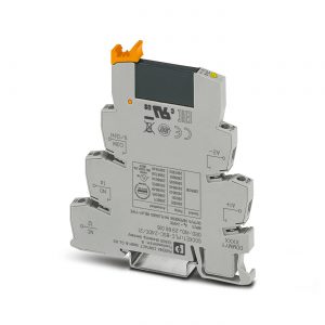
Coupling relay – PSR-PS20-1NO-1NC-24DC-SC – 2700356
Coupling relay for SIL 3 high and low-demand applications, couples digital output signals to the I/O, 1 enabling current path, 1 confirmation current path, 1 digital signal output, safe state off applications, test pulse filter, fixed screw terminal block
Dimensions
Width 6.8 mm
Height 93.1 mm
Depth 102.5 mm
Back to top
Ambient conditions
Ambient temperature (operation) -40 °C … 70 °C (observe derating)
Ambient temperature (storage/transport) -40 °C … 85 °C
Max. permissible relative humidity (operation) 75 % (on average, 85% infrequently, non-condensing)
Max. permissible humidity (storage/transport) 75 % (on average, 85% infrequently, non-condensing)
Maximum altitude ≤ 2000 m (Above sea level)
Back to top
Power supply
Designation A1/A2
Rated control circuit supply voltage US 24 V DC -15 % / +10 %
20.4 V DC … 26.4 V DC
Rated control supply current IS typ. 45 mA
Input voltage range “0” signal 0 V DC … 5 V DC (for safe Off)
Input current range “0” signal 0 mA … 2 mA (for safe Off)
Power consumption at US typ. 1.08 W
Inrush current typ. 400 mA (Δt < 10 µs at Us)
Filter time max. 2 ms (at A1-A2; test pulse width)
≥ 100 ms (at A1-A2; test pulse rate)
Protective circuit Serial protection against polarity reversal Suppressor diode 33 V
Designation 21/A2
Diagnostic supply voltage UD 24 V DC -15 % / +10 % (21/A2)
Input current at UD 6 mA (at 21-A2 for UD; depending on load + 100 mA at M1 and 22)
Inrush current at UD typ. 2.5 A (Δt < 20 µs at UD)
Protective circuit Serial protection against polarity reversal Suppressor diode 38 V
Back to top
Relay outputs: enabling current path
Output name Enabling current path
Output description 2 N/O contacts in series, without delay, floating
Number of outputs 1 (safety-related N/O contacts: 13/14)
Contact type 1 enabling current path
Contact material AgSnO2
Switching voltage min. 12 V AC/DC
max. 250 V AC/DC (Observe the load curve)
Limiting continuous current 6 A (High demand)
4 A (Low demand)
Inrush current min. 3 mA
max. 6 A
Sq. Total current 36 A2 (observe derating)
Switching capacity min. 60 mW
Switching frequency max. 1 Hz
Mechanical service life 10x 106 cycles
Switching capacity according to IEC 60947-5-1 4 A (24 V (DC13))
5 A (250 V (AC15))
Output fuse 6 A gL/gG
4 A gL/gG (for low-demand applications)
Back to top
Relay outputs: return current/signaling current path
Output name Confirmation current path
Output description 2 N/C contacts in series, without delay, not floating (reference ground: A2)
Number of outputs 1 (safety-related N/C contacts: 21/22)
Contact type 1 confirmation current path
Contact material AgCuNi, + Au
Switching voltage min. 20.4 V DC
max. 26.4 V DC
Limiting continuous current 100 mA
Inrush current min. 1 mA
max. 100 mA
Switching capacity min. 20 mW
Switching frequency max. 1 Hz
Mechanical service life 10x 106 cycles
Output fuse 150 mA Fast-blow
Back to top
Alarm outputs
Designation M1
Output description PNP
Number of outputs 1 (non-safety-related)
Voltage approx. 22 V DC (UD - 2 V)
Current max. 100 mA
Maximum inrush current 500 mA (Δt = 1 ms at Us)
Short-circuit protection no
Output fuse 150 mA fast blow
Back to top
Times
Typical pickup time at US < 100 ms (with Us when controlled via A1)
Typical release time at US < 35 ms (when controlled via A1)
Recovery time 500 ms
Back to top
General
Relay type Electromechanical relay with force-guided contacts in accordance with IEC/EN 61810-3
Nominal operating mode 100% operating factor
Net weight 69.773 g
Mounting position vertical, horizontal, with front of module upward
Mounting type DIN rail mounting
Assembly instructions See derating curve
Degree of protection IP20
Min. degree of protection of inst. location IP54
Housing material PBT
Housing color yellow
Operating voltage display 1 x yellow LED
Status display 2 x green LEDs
Indication 1 x red LED