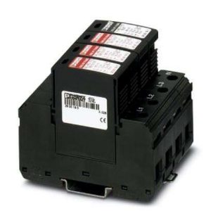
توضیحات
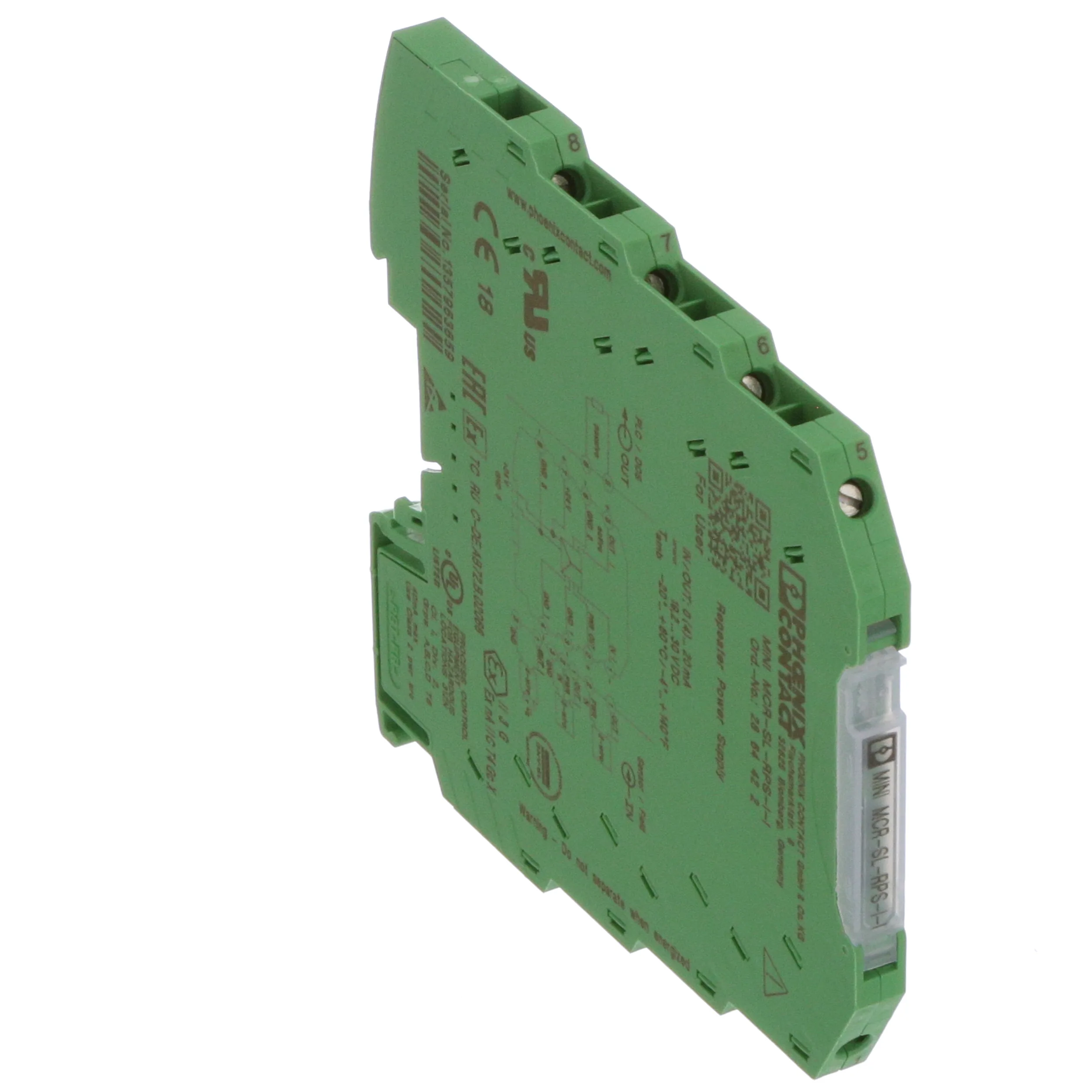
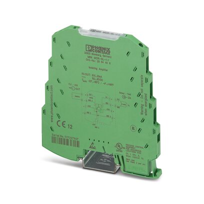
MCR repeater power supplies, screw connection, input signal: (0)4..20 mA, output signal: (0)4..20 mA
Dimensions
Width 6.2 mm
Height 93.1 mm
Depth 101.2 mm
Back to top
Ambient conditions
Ambient temperature (operation) -20 °C … 60 °C
Ambient temperature (storage/transport) -40 °C … 85 °C
Maximum altitude ≤ 2000 m
Permissible humidity (operation) 5 % … 95 % (non-condensing)
Degree of protection IP20
Noise immunity EN 61000-6-2 When being exposed to interference, there may be minimal deviations.
Back to top
Input data
Designation Current input
Description of the input Sensor circuit
Number of inputs 1
Current input signal 0 mA … 20 mA (isolator operation)
4 mA … 20 mA (repeater power supply and isolator operation)
Max. input current 28 mA
Input resistance current input approx. 50 Ω
Transmitter supply voltage UB – max. 4.5 V for load 0 mA … 20 mA
Transmitter supply voltage range 14.7 V DC … 25.5 V DC
Back to top
Output data
Output name Current output
Number of outputs 1
Current output signal 0 mA … 20 mA (isolator operation)
4 mA … 20 mA (repeater power supply and isolator operation)
Max. output current 28 mA
Load/output load current output ≤ 500 Ω (I = 20 mA)
Ripple < 20 mVrms (at 500 Ω)
Transmission Behavior 1:1 to input signal
Back to top
Power supply
Nominal supply voltage 24 V DC
Supply voltage range 19.2 V DC ... 30 V DC (The DIN rail bus connector (ME 6,2 TBUS-2 1,5/5-ST-3,81 GN, Item No. 2869728) can be used to bridge the supply voltage. It can be snapped onto a 35 mm DIN rail according to EN 60715))
Power consumption < 900 mW (at 24 V DC and in repeater power supply operation)
< 600 mW (at 24 V DC and in isolator operation)
Back to top
Connection data
Connection method Screw connection
Stripping length 12 mm
Screw thread M3
Conductor cross section solid 0.2 mm² ... 2.5 mm²
Conductor cross section flexible 0.2 mm² ... 2.5 mm²
Conductor cross section AWG 26 ... 12
Back to top
General
No. of channels 1
Maximum transmission error ≤ 0.2 % (of final value)
Transmission error, typical ≤ 0.1 % (of final value)
Maximum temperature coefficient < 0.01 %/K
Temperature coefficient, typical < 0.002 %/K
Limit frequency (3 dB) approx. 100 Hz
Step response (10-90%) approx. 3.5 ms
Protective circuit Transient protection
Electrical isolation Basic insulation according to EN 61010
Overvoltage category II
Degree of pollution 2
Rated insulation voltage 50 V AC/DC
Test voltage, input/output/supply 1.5 kV (50 Hz, 1 min.)
Electromagnetic compatibility Conformance with EMC directive
Noise emission EN 61000-6-4
Noise immunity EN 61000-6-2 When being exposed to interference, there may be minimal deviations.
Housing material PBT
Mounting position any
Assembly instructions To bridge the supply voltage, the DIN rail connector (ME 6,2 TBUS-2 1,5/5-ST-3,81 GN, Item No. 2869728) can be used. It can be snapped onto a 35 mm DIN rail according to EN 60715.
Fire protection for rail vehicles (DIN EN 45545-2) R22 HL 1 - HL 2
Fire protection for rail vehicles (DIN EN 45545-2) R23 HL 1 - HL 2
Fire protection for rail vehicles (DIN EN 45545-2) R24 HL 1 - HL 2

